PLC and serial to Ethernet, serial to WIFI, MODBUS485 to Ethernet, RS485 to MODBUS gateway protocol communication between
Time:2017-04-06 17:45:57
PLC in the actual application, most of the data through the Ethernet to collect, the uplink and downlink instruction control. PLC in the actual use of the agreement, most of them are running 485MODBUS RTU, ASCII, MODBUS TCP / ip, MODBUS RTU to TCP / IP; then the market a lot of serial server can not be used. According to the actual requirements of R & D and production for the above agreement of the serial interface server, can solve a lot of customer requirements, the use of the product in the process without complex configuration, simple to use. Use the configuration as follows: Product Name: Industrial 232/485 to Ethernet two-way serial server (support Modbus) Specifications Model: ZP-8621 Product Name: Industrial grade 232 to WiFi two-way serial port server (support Modbus) Specifications Model: ZP-8811
Siemens S7-200
In the use of Siemens S7-200, without adding other communication interface module, the Zijin Bridge software can communicate with the S7-200 direct communication PPI protocol. However, this communication method due to the communication protocol itself is limited, in the communication data more, the communication speed is relatively slow, the use of Modbus protocol communication speed can be increased by about twice. Here to introduce how to use the Modbus protocol to establish S7-200 and Zijin Bridge software communication between:
Hardware connection When using the Modbus protocol, the communication between the computer and the S7-200 can be done directly using the PPI communication cable. But if the communication distance is far, or need to connect multiple S7-200 to a communication bus, we can through the following methods to prepare the communication link.
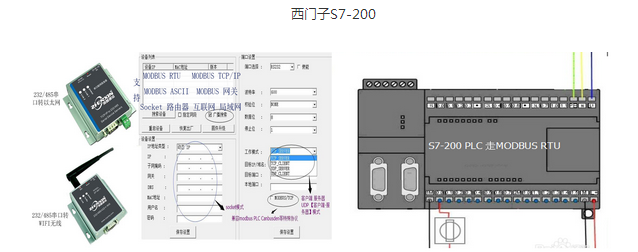
Match a computer communication port Since the physical layer of the S7-200 communication port uses the RS-485 communication specification, we need to add an RS-485 communication port on the computer side to establish communication with the computer. If the computer is idle serial port, we can choose an RS-232 to RS-484 converter can be; if there is no idle serial port, we through the computer to add an RS-485 communication card can also; now many computers have USB Mouth, we can also connect a USB to RS-485 converter on the computer.
Connect the communication cable The S7-200 communication port is a 9-hole (famel) D-type plug, S7-200 communication port (port 0) and RS-485 board or RS-485 / RS-232 converter wiring, as shown below :
Programming and setting of S7-200 By default, the communication port of the S7-200 does not support the Modbus protocol. To achieve Modbus communication, the Modbus communication subroutine must be called in the main program module of the PLC. The Modbus communication subroutine can be obtained from the "STEP 7-Micro / WIN Add-On: Instruction Library" (STEP 7-Micro / WIN Accessories: Instruction Library). After installing the "STEP 7-Micro / WIN Attachment: Instruction Library", we can find "Modbus Protocol" below the navigation tree "Instruction / Library". MBUS_INIT and MBUS_SLAVE are included in the following subroutine. MBUS_INIT is used to initialize Modbus communication. MBUS_SLAVE is used to provide Modbus slave communication service on the specified port. Under the introduction of how the main program in the relevant subroutine and environmental parameters set:
Call the Modbus communication initialization command First create a trigger condition for the MBUS_INIT command (trigger only once), eg SM0.1; drag the MBUS_INIT instruction to the main block from the navigation tree "Instruction / Library / Modbus Protocol" below. Then is the correct set MBUS_INIT call parameters and the implementation of the results of the output address, we can set up as shown below Initialize the call process:
Baud: Communication baud rate, 1200, 2400, 4800, 9600, 19200, 38400, 7600 or 11520.
Parity: check mode, 0 - no parity; 1 odd parity; 2 even parity.
Delay: The end time of the message, 0 ~ 32767, and the wired connection is set to 0.
MaxIQ: 0 to 128, the number of I or Q mapped in the discrete input register or discrete output register. Suggested as: 128.
Max: 0 ~ 32; mapped to the analog input register AIW number; CPU 221 is 0, CPU 222 is 16, CPU 224, 226 and 226XM are 32.
MaxHold: The number of registers in the memory register in the holding register.
Zijin Bridge Software Configuration After the completion of PLC programming and preparation, but also the preparation of the Zijin Bridge software, so as to obtain, process, detect, store and display the corresponding data. The configuration process is divided into two steps: (1) equipment configuration, that is, to establish a logical device corresponding to the PLC; (2) point configuration, that is, the establishment of process database point process parameters and PLC variables in the corresponding relationship, Thus using the point of their own functions for processing, detection and storage. Of course, the process data should be displayed on the computer to the user, but also interactive interface (window) configuration. But this process is the same for all applications, and it is not introduced here.
Equipment configuration The configuration of the device is based on the communication protocol used by the PLC and the node address, port attribute, etc., to define the communication parameters. Into the Zijin Bridge development environment, switch the navigation tree to the "database", select "Device Driver / MODBUS / MODBUS" in the navigation tree, click the right mouse button, select "Add Device Driver" in the single menu, The dialog box will pop up: In the dialog box, enter the device name, device address (in the PLC MBUS_INIT initialization Addr parameter consistent), select the serial number, and set (click the "set" button) port properties, use it and PLC MBUS_INIT command set the same. Click "Next": In the Modbus Device Definition dialog box, select "RTU" for the protocol type, "32-bit" for the memory type (ie, the data format for the long and floating 4-byte data is high, The Click the "Finish" button, the device configuration is complete. Point configuration and I / O connection to complete the point configuration but also point to configure the I / O connection, so as to the variables in the PLC mapping to the Zijin Bridge software. Into the Zijin Bridge development environment, the navigation tree to switch to the "database" in the navigation tree double-click "point configuration", enter the point group window:
Select the type of point, set the point, set the general parameters of the basic configuration of the point configuration, for all applications are the same, here is not described in detail. The following highlights the I / O connection and the corresponding correspondence with the variable. Here is an example of an I / O connection with an analog I / O point. After creating a new analog I / O point, enter the name and switch to the "Data Connection" property page:
Select the device created in the previous step from the device list box of the attribute, such as MOD, and click the Add Connection Item button to enter the Modbus Group Point dialog box:
Here the "memory area", "offset" and "data format" is part of the memory with the PLC type and address corresponding. For Modbus memory can not correspond to the PLC memory type, if you need to upload to the process database, you can first move to the V memory area, and then read through the V memory area.

 sales
sales 